

DC Motor Drive SCR Failure: Ultrasound and Vibration
A DC Drive is powered by an AC Power Source. To get constant voltage, Silicon Controlled Rectifiers (SCRs) are used. The following case study looks at a full-wave rectified DC Drive, meaning there are 6 AC signals & 6 SCRs powering the system. The DC Drive is connected to a fan pump by a coupling.
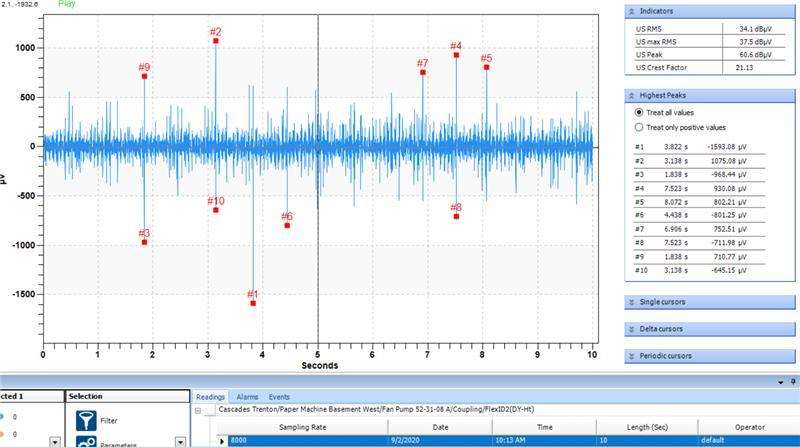
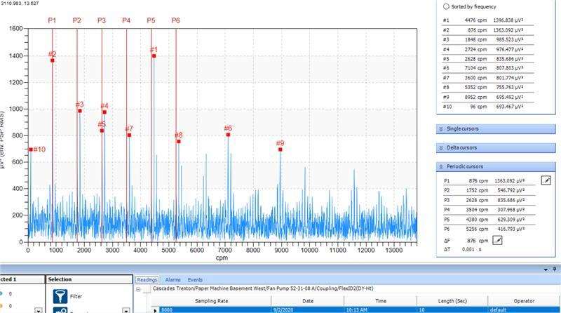
The following are the ultrasound Time Waveform and FFT were recorded using an airborne ultrasound sensor on the systems coupling.
By observing the ultrasound time waveform (Figure 1), we see the coupling is in poor condition with lots of impacting. In the ultrasound FFT (Figure 2) there is a high peak at 1 X RPM, indicating looseness. Also, inconsistent, yet repetitive impacting, caused by fluctuations in rotational speed.
Performing further analysis with a vibration analyzer lead SDT's Partnered Ultrasound Team to a discovery as to why the DC Motor had fluctuating run speed. In full wave rectified DC Drive Systems, firing cards control 2 SCRs.When a Firing Card Fails on a DC Motor, 1/3rd of the motor's power is lost, resulting in momentary changes in rotational speed. This can be seen in the vibration spectrum with high amplitudes at 1/3 X SCR, or 7200 CPM (120Hz) (In North America).
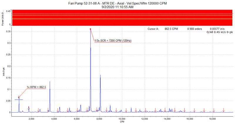
Using two condition monitoring technologies, our Partnered Ultrasound Team was able to fully diagnose this asset. Ultrasound to find the broken coupling and vibration to find 2 blown SCR’s on a Full-Wave Rectified DC Drive System.