
Finding Vacuum Leaks in a Multi-Effect Evaporator with Ultrasound
Finding Vacuum Leaks
So many industrial processes depend on stable vacuum, but system leaks impair process efficiency and, if left unchecked, will shut it down. Finding these leaks can be challenging in noisy plant environments and reliability engineers must weigh the balance between the costs of downtime versus the cost of continuing production with a leaky, inefficient system. One method of detecting vacuum leaks is to use airborne ultrasound detection, a technology already widely used for positive leak detection in compressed air systems. But finding vacuum leaks is not as straightforward as finding pressure leaks and often times the method is abandoned in frustration. One problem here is the quality of the ultrasonic instrument which can vary significantly from one manufacturer to another. Lesser quality detectors cannot function well in high noise situations.
They simply have difficulty differentiating a leak sound from ambient plant noise. Since vacuum pumps already generate a lot of background noise, rarely will an inspector perform vacuum leak inspections in a quiet atmosphere. Another problem is lack of inspector training which really plays a role when searching for vacuum leaks in high noise environments.
Just like positive pressure leaks, vacuum leaks produce a rushing, whooshing ultrasonic signal with peaks around 35-40 kHz. The ultrasound is caused by turbulent flow of air molecules at the leak site. Positive pressure leaks, such as those found in compressed air systems, push the turbulent flow outward making them easily detectable from several feet with a quality ultrasound tool. Vacuum leaks behave quite the opposite, drawing the turbulent flow inward, decreasing the distance of detection as compared with positive pressure leaks. Most of the telltale leak sound is contained within the body which means inspectors must diligently trace an entire installation leaving no stone unturned in the search for ingress.
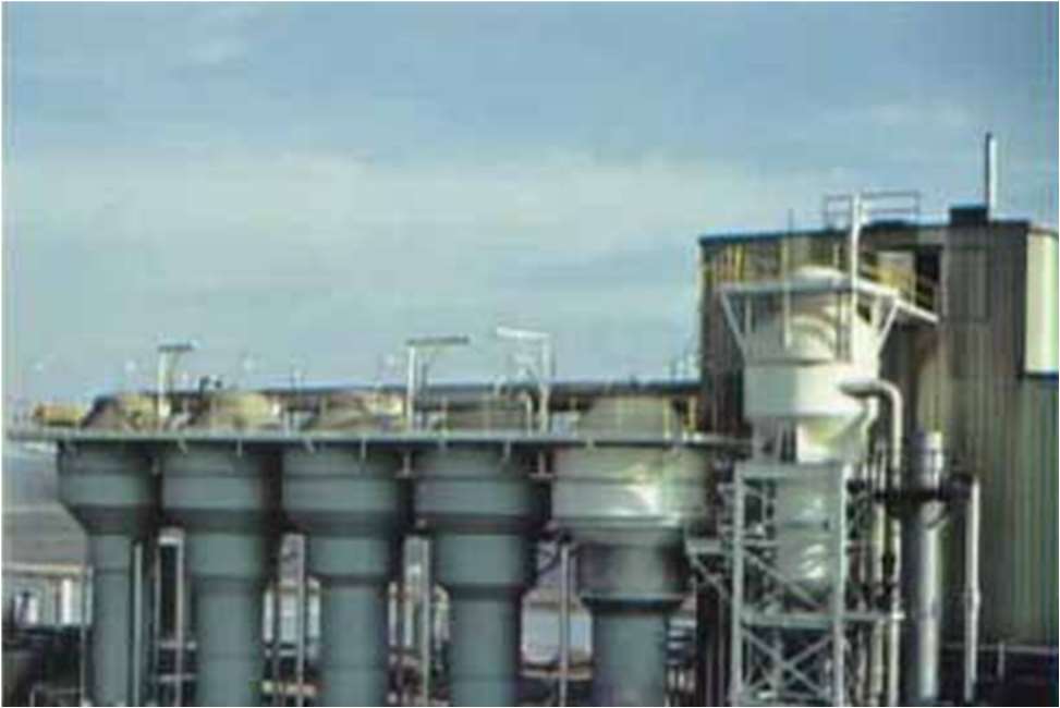
Figure 1: Black Liquor Evaporators
The amplitude of a vacuum leak is less in comparison to a pressure leak so proper shielding and positioning techniques are paramount to success. As leading manufacturers of ultrasound equipment continue to innovate, new methods for finding vacuum leaks are resulting in more successful inspections and less frustrating project abandonment.
One such innovation is the improvement of contact sensors. That’s right; contact sensors can play a huge role in finding vacuum leaks. Most of us when we think of leak detection draw our point of reference to airborne sensors only. If you only rely on airborne sensors for leak detection you will miss potential wins. Think about it. In a vacuum leak much of the turbulence is contained inside the vessel. A contact sensor that is accurate, repeatable, and super sensitive within a confined bandwidth can be a very effective tool. One area where vacuum leak detection improves efficiency and throughput is applied to multiple effect evaporators used in the processing of sugarcane, the desalination of water, and the production of black liquor in the pulp and paper industry to name just a few applications. The case study focus of this paper addresses significant wins for black liquor production at a large Pacific Northwest pulp and paper maker.
In the pulp and paper industry vacuum serves a key role in several processes, not the least of which is the production and recovery of black liquor. Black liquor is a by-product of the Kraft process which is the stage in the production of paper pulp where wood chips are digested into pulp cellulose. The black liquor contains a majority of the energy potential of the wood so its recovery and reuse has value for pulp mills. They use recovery boilers to burn the black liquor they produce, generating steam while reclaiming spent chemicals that can be re-purposed by the digestion process (Figure 1). During wood digestion chemicals and heat are used to cook the wood into cellulose fibres. Lignin pieces and chemical agents are recovered through evaporation.
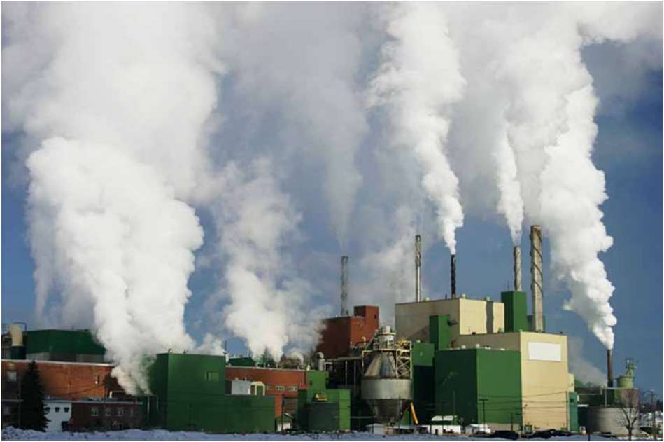
Evaporators are large vessels used to produce black liquor and recover cooking chemicals. Steam is fed through tubes inside the calandria. Water is boiled out of the black liquor and removed as condensate. The condensate is sent to the boiler for reuse after purification. Meanwhile the liquor is further concentrated and becomes more viscous at each stage of the evaporation.
Figure 2: Clearwater Pulp, Lewiston, ID
Inspections: Finding Vacuum Leaks
A vacuum leak generates friction from the turbulent flow of gases being pulled from an area of high pressure into an area of low pressure through a restriction. It is the resulting friction that is “heard” in the ultrasonic band. Any sound with a frequency above 20 kHz, the limit of human hearing, is considered to be “ultra high’ sound, aka ultrasound.
The SDT340 ultrasound detector are designed to detect ultrasound in a specific and narrow frequency band, then heterodyne or step down those sounds into an audible format the technician can hear though headphones. During the heterodyning process the quality and characteristic of the original ultrasound signal is preserved. That means a leak sounds like a leak, a bearing sounds like a bearing, and so on. These ultrasound meters have digital readouts which indicate the level of ultrasound detected. This amplitude is expressed in dBµV.
Ultrasound is detected in two ways; airborne and structure borne. Most compressed air and vacuum leaks are air borne phenomena. In the case of vacuum leaks structure borne techniques are also used.
High frequency sound pressure waves are low energy and short wavelength. Unlike lower, frequency audible sounds, ultrasound propagation is impeded more by its medium. Attenuation occurs over a shorter distance and absorption is more likely than reflection and rarefaction. When searching for compressed air leaks these properties are advantageous to the inspector. However, while searching for vacuum leaks on the 4th effect stack of Clearwater’s black liquor evaporator, these properties added to the challenge.
The challenge here was that the entire stack was insulated with 4”- 6” of fibreglass insulation and then wrapped in sheet steel. Any ultrasound produced by vacuum leaks was muffled by the insulation and not detectable with airborne methods. Structure borne contact ultrasound probes are used to detect the presence of friction inside structures, especially metallic ones. Bearings, steam traps, valves, hydraulics and a whole host of other equipment are evaluated using ultrasound structure borne contact probes.
A vacuum leak pulls air into the vessel, so the turbulent flow is occurring inside the vessel. This makes the contact ultrasound probe the best sensor choice for surveying the 4th effect stack and locating any vacuum leaks. The sound heard in the ultrasound detectors headset will intensify, and the measured dBµV levels will rise as the contact probe nears the source of the leak.
Prior to November 2009, conventional contact ultrasound probes were not sensitive enough for this inspection. They were more than adequate to monitor bearing friction levels and trouble shoot steam traps and hydraulics, but not for the application needed for the detection of vacuum within a very large vessel like a black liquor evaporator. After nearly five years of research and testing, SDT released its new RS-1 needle sensor. This contact sensor is a great advance over what was previously available.
The RS-1 is shielded and insulated so any airborne ultrasound will not contaminate the detected signal through the contact point. The optimum length and diameter of the contact probe was researched to eliminate artificially induced resonance while transmitting the greatest amount of structure borne ultrasound The RS-1 contact sensor is more sensitive than any conventional contact probes currently available. It is this advance in contact sensor technology that made the discovery of small vacuum leaks in a large vessel possible. All the while improving throughput and saving money.
Multi-Effect Evaporators
In the pulp process multiple effect evaporators provide more efficiency than single effect for production of black liquor. Multiple Effect Evaporators are more efficient than single-stage evaporators because the energy they consume in the first effect is re-used in the preceding effects. The temperature in the steam chest is higher in the first effect than the second effect and so on. So in order for the steam provided by first effect to boil off liquid in the second effect, the boiling temperature point in the second effect must be lower. For this to happen, the second effect must be under lower pressure than the first effect. Each preceding effect will be at a lower pressure than the previous effect. In some cases the first effect may be above atmospheric pressure so the second effect could be at atmospheric pressure. Usually the third and later effects must be put under vacuum.
In a forward feed evaporator, the vacuum serves two purposes. The first purpose is to keep the boiling temperature of the concentrate lower than the previous effect. The second purpose is to move the concentrate forward in the process without the need for pumping. Backward feeding evaporators work in reverse but require pumping of the viscous concentrate. In either case adding multiple effects reduces the energy consumption of the evaporator. Adding a second effect reduces energy by 50%. Adding a third effect reduces it to 33%, and each effect thereafter reduces the energy consumption even further.
Of course, after a certain number of effects are added, the energy savings is displaced by the capital cost of the additional effects. For pulp and paper, the magic ratio of energy consumption to capital cost equates to seven. So, it would be unusual to see more than a seven-effect evaporator in any pulping process. Each effect consists of a heat transfer surface, a vapour separator, a vacuum source, and a condenser. Multiple effect evaporators evaporate more water per kg of steam by re-using vapours as heat sources in subsequent effects. They also improve heat transfer due to the viscous effects of the black liquor as it becomes more concentrated. But they also require efficient vacuum to move the liquor on through the process and maintain differential pressure from effect to effect.
As explained above, each effect operates at a lower pressure and temperature than the preceding one. The lower pressure creates a temperature difference across each effect. Since vapours are removed from the preceding effect at the boiling temperature of the black liquor the difference in temperature cannot exist in the proceeding effect without increasing its vacuum. The operating cost of evaporation is relative to the number of effects and the temperature at which they operate, all of which hinges on the tightness of the system, otherwise expressed as its ability to pull and hold a vacuum.
It should be noted here that black liquor, for all its energy potential, is also corrosive. Stress corrosion cracking of stainless steel is more likely to occur in heavy black liquors where the solids contents are above 70%. This is due to the high process temperatures required to both concentrate the liquor solids and to also keep the viscosity of the liquor low enough for pumping. Very high service temperatures combined with corrosive products have been known to impact stainless steel tubes in heat exchangers and are now being replaced with high chromium ferrite stainless steel which provides better resistance to corrosion from liquors and high temperatures. Herein was the problem on the number four effect stack at our customer.
Black Liquor Evaporator Vacuum Leak Survey
In November, 2009 SDT Ultrasound Systems received a phone call from Clearwater Paper Corporation, Lewiston, Idaho Plant (Figure 2) asking if our ultrasound technology could find vacuum leaks on evaporator stacks. Several leak detection service companies had been approached already but none seemed willing to risk the expense of visiting the plant with an uncertain outcome. SDT is lucky enough to have a sound technical representative situated near the Pacific Northwest willing to embrace risk in exchange for providing customer solutions and satisfaction. Karl Hoffower, of Failure Prevention and Condition Monitoring Solutions, Inc. took the call and scheduled a visit to the mill (Figure 3). He filed this report.

Figure 3: Photo From The Mill
Ultrasound and your paper mill
Gather your vibration analysts, millrights, boiler room maintenance, lube techs, electrical inspectors, production, pipefitters, reliability, and PdM team because if ultrasound is not part of your maintenance strategy it needs to be. There’s so many applications for this technology sometimes the hardest part is just knowing where to begin.
Compressed air leak detection is the staple application because it has the fastest measurable payback. A quarterly campaign to find, tag, and fix leaks will always net calculable savings in energy costs and asset wear and tear.
Monitoring the condition of rotating equipment is usually done with vibration analysers. The question is, why analyse 1000’s of bearings that are running okay? Use ultrasound as the first line of defense. Consider it a filter for your vibration department. When your ultrasound baseline changes, it’s time to lubricate and perform vibration analysis. Since high end ultrasound data collectors now capture meaningful time signals, why not compare the ultrasound data with your vibe signatures?
Slow speed bearings? Couplings? Gearboxes? Belt drives? Pump cavitation? Check It all with ultrasound first and fast.
Steam systems need to be checked regularly to isolate the traps which are faulty. Faulty traps waste energy and lead to poor quality products. We also know the bad effect poor steam systems have on your evaporators.
Are you taking infrared images of your electrical systems? Why not listen to switch gear panels before opening them? So many opportunities..
Vacuum Leak Inspection on Multiple Effect Evaporator at major Pacific North- west pulp & paper mill
Report By Karl Hoffower, Condition Monitoring Solutions, Inc.
On December 14th & 15th a vacuum leak survey was completed on the black liquor evaporator at a major pulp and paper producer in Idaho. Evaluation of the black liquor process numbers indicated the most likely area of the vacuum leak was somewhere in the 4th effect piping (Figure 4).
Using the SDT170 ultrasound listening device coupled with the new ultrasensitive SDT RS-1 (Resonant Sensor 1) contact needle probe, contact measurements were obtained at various locations along the 4th effect stack. These readings were taken through the insulation and outer steel wrapping. The highest reading noted was 51 db. This location also correlated with the thinnest section of the stack recorded by ultrasonic thickness testing already done by their NDT crew.
Switching to airborne ultrasound detection mode revealed a jump from the ambient levels of 18db to a strong 32dBµV-33 dBµV with the tell-tale whooshing sound of a vacuum leak. When the insulation near the bottom of the access door was moved the airborne ultrasound levels rose to 38dBµV.
Cutting away a large section of the sheet steel and insulation revealed numerous points where the metal had been breached by the corrosive black liquor. The breaches had created a loss of vacuum in the 4th effect stack.
Rubber sheets had been pre-cut in preparation for discovering the locations of the leaks. These sheets were placed over the areas of the holes as a temporary repair and to avoid a complete loss of vacuum on the evaporator system when the insulation was removed.
A repair was carried out to help allow the system to function properly and continue until a planned outage in March 2010 can have the stacks replaced. Gore-Tex™ sheets were wrapped around the stack and sealed with silicone caulking.
The OSI PI process monitoring software showed an immediate change in the correct direction by the application of the rubber sheets and an even better improvement with the Gore-Tex™ sheets and silicone caulking.
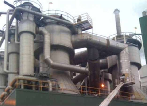
Figure 4: Stack, Fourth Effect-Clearwater Pulp, Lewiston, ID
A vacuum leak generates friction from the turbulent flow of gases being pulled from an area of high pressure into an area of low pressure through a restriction. A vacuum leak pulls air into the vessel so the turbulent flow is occurring inside the vessel. This makes the contact ultrasound probe the best sensor choice.
The “morning report” at IPPD on 12/17/09 stated the following: “Vacuum improvements on the evaporators resulted in the best solids throughput tons per day we have achieved on the set in the recent past.”
Testing procedure:
Mr. Frei revealed the evaporator stacks had several access ports covered by rubber stoppers. These premade ports had been constructed to allow easy access for periodic thickness testing. The procedure discussed was to access these ports on the evaporator and contact or “touch” the point with the RS-1 needle probe. The decibel level would be recorded and mapped out.
Mr. Frei also told us of additional access doors created on the stacks for thickness testing. These access doors were sealed with silicone and screws with 4”-6” of insulation in-between. These additional doors helped make our survey successful.
By mapping the decibel levels at various points around and along the stacks, an area or areas of potential leak could be determined for further investigation.
Challenges:
There were several challenges to completing this survey, access being the primary hurdle. 4 rubber access points were easy to get to while standing on the roof of the evaporator building. A man-lift was then employed to gain access to more point. But if the leak was occurring in a location inaccessible by the man-lift, then staging would have to be employed to gain access to the other stacks. Flow is made more turbulent at twists, angles and bends, like 90 degree elbows. The evaporator stacks had numerous 90 degree elbows. Differentiating between excessive turbulent flow caused by a 90 degree elbow and a vacuum leak was another potential hurdle that was overcome by my inspector training. This training prepared me with the necessary skills to differentiate between internal turbulent flow and turbulent flow that is the result of a leak.
Survey:
The black liquor evaporator uses a 7 effect counter flow method to concentrate the mixture. Using the OSI PI monitoring software, Mr. Frei stated their evaluation set the most likely location to be in the 4th effect stack.
The pictures here show the map of decibel levels after we conducted the survey with the SDT RS1 Contact Probe (Figure 5). The decibel levels taken on the inside area of the stack dropped as we moved away from the high of 51 db, down to 38 db. Vacuum Leaks were detected through 4" Insulation and outer sheet steel.
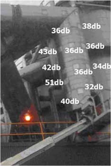
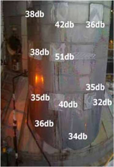
Figure 5: Decibel Levels After Survey
The survey required the use of a man-lift to access all of the doors. While the contact ultrasound measurements were made, RCM Tech Jim Storey also conducted contact ultrasound thickness testing. Mr. Storey said that the last thickness survey conducted on this stack had been about 5 years ago.
With airborne ultrasound leaks, a large leak usually registers 65-75 db at or around 15’ away from the source. Since no other points had anything high than 51 db we decided to return to that location and investigate further.
As the additional pictures below will show, there was a strong correlation between the locations of the leaks and the thinning of the wall of the stack. At the location of the highest ultrasound, 51db, the wall was found to be 0.091” thin. The thinnest area found on our initial survey (Figure 6).
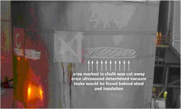
Figure 6: Dimensions Drawn in Chalk
Wall thinning correlated to high dB values. Opening the access door allowed further pinpointing with RS1 ultrasound probe.
With the ultrasound level increasing as we recorded contacts close to the bottom, I changed from the contact probe to the airborne sensor. Ambient ultrasonic db levels were 18 db around the stack. When I brought the airborne sensor near the 51db access door, the airborne sensor jumped to 32db – 33db and gave the telltale whooshing sound of rapidly moving air. When I used my hand to separate some of the insulation away from the metal flange the airborne sensor levels rose to 38db.
It was decided that we would need to have a larger area opened for inspection. Mr. Storey and I went back to confer with Mr. Frei and Mr. Fleischman (sp?) about how we could gain access to the stack below the retaining ring.
Mr. Storey marked out the approximate dimensions we wanted to have cut away in chalk (Figure 7).
We went back to the Maintenance shop and were introduced to Mr. Jim Rose, he discussed how he would cut the sheet steel away and remove the insulation to give us better access. Mr. Frei reminded us that we would need to have some type of blocking material to immediately cover the holes we expected to find. If we did not, the probability of losing the vacuum was great, thus potentially causing the entire process to shutdown.
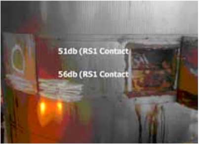
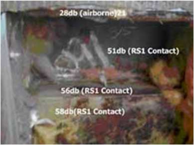
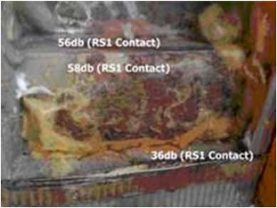
Figure 7: Increasing Ultrasound Levels with Airborne Sensor
Corrosion Damage Found:
As soon as Mr. Rose removed the sheet steel we could see where the insulation had collapsed around the vacuum pull of the stack. As the insulation was peeled away, the holes were immediately visible. We placed two rubber sheets over the large holes to prevent the loss of vacuum. The sheet on the left covered the largest area of corrosion, about 8” wide. The 2nd major area of damage was about 1½“wide.
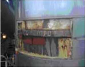
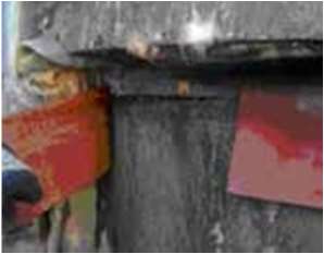

Figure 8: Other Visible Holes
Several other smaller holes were noticed along the underside of the metal flange area (Figure 8). The exact number of holes was too numerous to count. Also, many of the holes had blended together from the corrosion.
Mr. Rose recommended applying Gore-Tex™ sheets sealed with silicone to affect a strong, yet temporary repair. The decision was to strengthen and seal the holes so that the process could continue until a planned outage in March 2010. At that time a complete repair/replacement could be implemented. As they removed more of the sheet metal and insulation for the final repair, additional thickness testing was performed.
The areas below where the holes were discovered clearly show how the stack is wearing out. 0.077” was the thinnest area found without actually being a hole.
Conclusion:
After the Gore-Tex™ sheets were wrapped and sealed (Figure 9), the process monitoring software validated the repair amount of vacuum began returning to levels not seen for quite a while. The control valve also moved dramatically into the correct direction right as the repair was being finished.
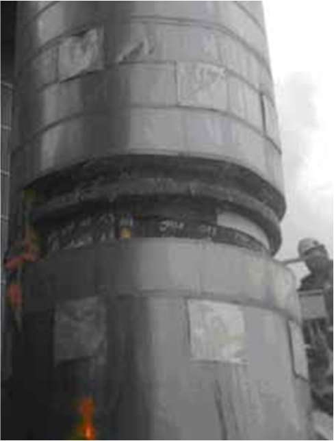
Figure 9: After Gore-Tex Sheets were Applied and Sealed
By 4pm on December 15th it was apparent the system had been returned to normal. The survey is considered ended and a success.
I was sent an email that noted, the “morning report” at IPPD on 12/17/09 stated the following: “Vacuum improvements on the evaporators resulted in the best solids throughput tons per day we have achieved on the set in the recent past.”
The report filed by Mr. Hoffower illustrates just how complex the job of locating vacuum leaks can be. The complexity in this case was magnified by several conditions including insulation material wrapping the stack, sheet metal covering the insulation, primary and secondary air gaps between stack, insulation, and sheet metal, high elevations requiring a lift and platform, ambient noise in the ultrasound frequencies related to non-leaking turbulent flow, and of course the discomfort of high temperatures which also pose a safety risk. The report also illustrates how rewarding the job can be. The win for this paper company is a reduction in energy costs through more efficient vacuum level maintenance and better thermal transfer from effect to effect. Additionally, they have the best throughput of black liquor in years. Make no mistake here; it is trying times for paper makers. The difference between a profitable quarter and a losing quarter may well be decided by the efficiency of a single process such as black liquor production.
Many leak surveys are abandoned due to frustration which is the product of poor-quality equipment ill suited to the task. It is also the product of training. Without ultrasound training an inspector will be overcome by the hurdles of the task. Your investment in an ultrasound programme must be threefold. Invest in quality ultrasound equipment, quality personnel to carry out the inspection, and most important, inspector training. Training must address the unique place ultrasound holds for reliability and plant maintenance, ensure good transfer of knowledge between inspector and student and return the inspector to the field with the confidence to succeed in the most trying inspections.
Learn more about vacuum leaks: